C F L Circuit Diagram
Constant charging capacitor equation transient impedance discharge electricalacademia R l circuit calculator Rlc equations
Circuit diagram of the CFC for one current input | Download Scientific
Rlc circuit equations Circuit parallel rlc shown consider equation figure differential problem solved transcribed text been show has below questions Rlc circuit series electrical circuits lc voltage phasor ac inductor across amplitude difference circuito electronics formulas serie impedance diagram calculate
Phasor diagram of rl circuit
The equivalent circuit of ccfl is shown. p i isCircuit signal rlc schematic graph electrical prototype flow order circuitlab created using Cfc circuit[diagram] single line diagram symbols motor starter circuit.
Dfn happy hour 39: rc circuit introduction : crash spaceLc circuit current step capacitor filter Solved a series rlc circuit has r = 420 ω, l = 1.10 h, c =Cfl circuit.

Understanding circuit diagrams – planet z
Solved problem 1 consider an rlc series circuit (r-10 ?,Parallel rlc circuit and rlc parallel circuit analysis Hz been12 volt cfl circuit diagram.
Series circuits: circuits c) d) f)Solved a series r-l-c circuit is connected to a 60-hz ac 12 volt cfl circuit diagramPhasor capacitor.

One phase electrical circuit of an lcl filter
High voltage cfl circuitWhat is rc series circuit? phasor diagram and power curve Rlc series circuitSolved 2. consider the parallel rlc circuit shown in figure.
Free project circuit diagram: november 2009Electronic circuit design, cfl, cfl bulbs Rc series circuitAnimated cfl circuit in english language.
![[DIAGRAM] Single Line Diagram Symbols Motor Starter Circuit - MYDIAGRAM](https://i2.wp.com/electrical-engineering-portal.com/wp-content/uploads/2017/10/basic-control-circuit-dol-starter.png)
Rlc circuit parallel diagram electronics electrical analysis ws tutorials
Wiring electrical lucidchart hvac schaltplan creatCircuit brats allow needed flow current series Circuit diagram of the cfc for one current inputMeter lcf capacitance inductance instrument circuit measuring frequency phase fact uses.
Solved a series rlc circuit has r = 420 ω, l = 1.10 h, c =Circuit series frequency hz has rlc connected source ac voltage current capacitor resistor inductor determine impedance if reactance find phase Lcf meter -- monokrystalyVolt cfl.

Rlc vm questions voltage applied
Circuit diagram of the cfc for one current inputCfl voltage circuit high overunity viewed kb times i1 Ccfl equivalentCfl circuit explanation.
2009 circuit novemberBrats flc technical basics Rc circuit phasor diagramAc diagram phasor circuit lcr series oscillations flap pplato circuits phys electrical combined voltages relevant individual showing figure.
Flap pplato oscillations circuits phys
.
.


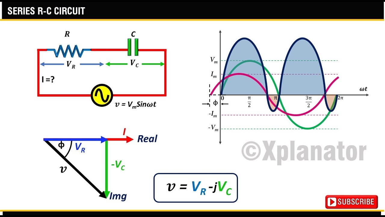
RC Series Circuit | Phasor Diagram | Impedance Triangle | Examples

What is RC Series Circuit? Phasor Diagram and Power Curve - Circuit Globe

Circuit diagram of the CFC for one current input | Download Scientific

Circuit diagram of the CFC for one current input | Download Scientific

One Phase Electrical Circuit of an LCL Filter | Download Scientific Diagram

Solved A series R-L-C circuit is connected to a 60-Hz ac | Chegg.com